UG-45: Nozzle Neck Thickness
Let first start with defining what is nozzle thickness and hub thickness as for self-reinforced nozzle this may become confusing.
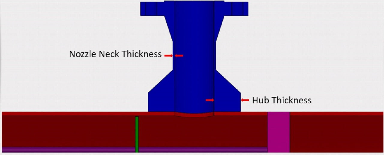
The nozzle neck is the pipe thickness as indicated in the below image. Hub thickness is the thickness of the self-reinforced part of the nozzle neck.
For the calculation of Nozzle Neck Thickness, we can divide the nozzle into two types:
⦁ Inspection or access Nozzles
⦁ Other Nozzles
Thickness calculation for Access or Inspection Nozzles:
![]() Just think, if we do not know any rule for nozzle thickness calculation, how we will design the nozzle?
Just think, if we do not know any rule for nozzle thickness calculation, how we will design the nozzle?
We know how to design a cylindrical shape, nozzle neck being a cylindrical shape if we apply our engineering judgement, we can use UG-27 and UG-28 to design it. Now let us see what code is saying:
Minimum Nozzle Neck Thickness for access or inspection opening (tUG-45)
tUG-45 = ta
ta = minimum neck thickness required for internal and external pressure using UG-27 and UG-28 (plus corrosion and threading allowance)
This is exactly what our engineering judgement said.
Thickness calculation for Other Nozzles:
One question will come in our mind that what is different in other nozzles, why we can not use same method? The reason is, these nozzles are connected with piping and may see some loads due to that connection. So calculation for these nozzles will have some additional steps.
Minimum Nozzle Neck Thickness for other nozzles (tUG-45)
tUG-45 = max (ta, tb)
ta = as calculated in previous step
tb = min [tb3, max (tb1, tb2)]
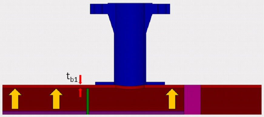
tb1 = Thickness of the shell or head where the nozzle is attached under internal pressure (plus corrosion allowance) required (assuming E = 1.0)
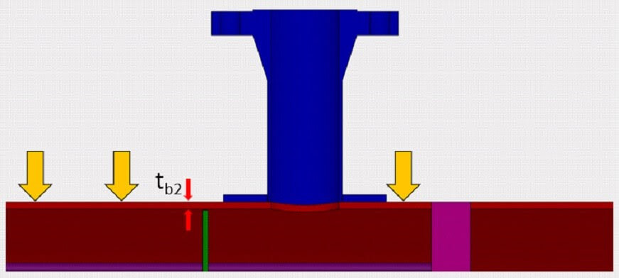
tb2 = Thickness of the shell or head where the nozzle is attached under external pressure (plus corrosion allowance) required (assuming E = 1.0)
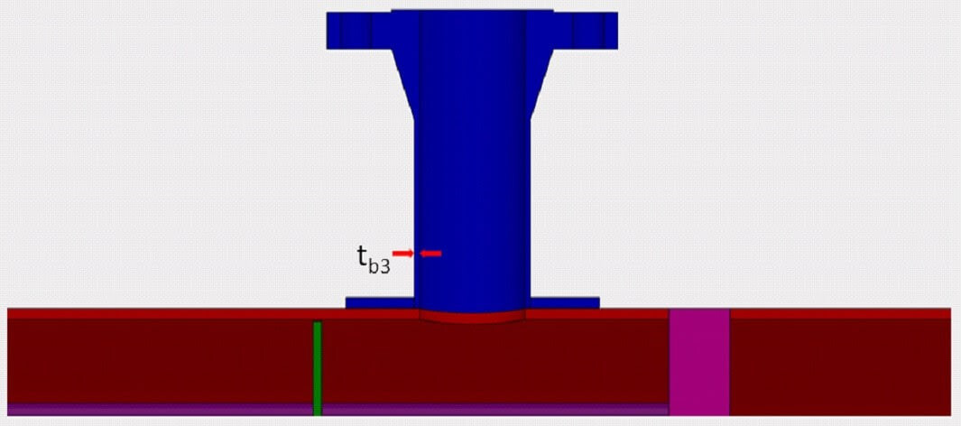
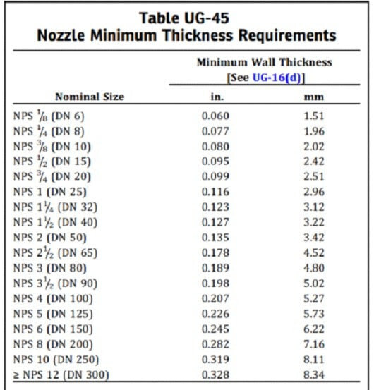
tb3 = Thickness given in Table UG-45 (plus corrosion allowance)
Example
Given
MOS of Vessel – SA 5186 Gr.70
MOS of Nozzle – SA 106 B
Internal Pressure, P – 1 MPa
External Pressure, Pe – 0.1 MPa
Vessel Diameter (D) – 2200 mm
Nozzle Diameter (d) – 200 mm
Vessel allowable stress, Sv – 138 MPa
Nozzle allowable stress Sn – 118 MPa
C – 3 mm
It is not an Inspection or access Nozzle.
Solution
Calculation of ta
ta = tug27+ C
ta = tug27+ 3
ta = 0.87 + 3
ta = 3.87 mm
Minimum Thickness as per UG – 16(b)
tr16b = 1.5 + C
tr16b = 1.5 + 3
tr16b = 4.5 mm
Calculation of tb1 {Thickness of shell where nozzle is attached under internal pressure (plus corrosion allowance) required (assuming E = 1.0) }
tb1 = max ( + C, tr16b)
tb1 = max ( + 3, 4.5)
tb1 = max (11.03, 4.5)
tb1 = 11.03 mm
Calculation of tb2 {Thickness of the shell where the nozzle is attached under external pressure (plus corrosion allowance) required (assuming E = 1.0)}
tb2 = max ( + C, tr16b)
tb2 = max ( + 3, 4.5)
tb2 = max (3.8, 4.5)
tb2 = 4.5 mm
Calculation of tb3 (Min thickness as per Table UG-45)
tb3 = Thickness from Table UG – 45 + C
tb3 = 7.16 + 3
tb3 = 10.16 mm
Calculation of tb
tb = min [tb3, max (tb1, tb2)]
tb = min [10.16, max (11.01, 4.5)]
tb = min [10.16, 11.01]
tb = 10.16 mm
Calculation of tUG-45
tUG-45 = max (ta, tb)
tUG-45 = max (3.85, 10.16)
tUG-45 = 10.16 mm
Minimum Nozzle Neck Thickness (tUG-45) = 10.16 mm